Lamar University Virtual Map
Research Project Title:
An Avatar-based Virtual Campus of Lamar University
This project is supported by the Department of Computer Science (DCS) and the Center for Innovation and Commercialization Entrepreneurship (CICE).
Project Team Members:
- Dr. Stefan Andrei(Coordinator) (Associate Professor at Lamar University)
- Ankur Shah (Graduate Student at Lamar University)
- Bharatkumar Tejwani (Graduate Student at Lamar University)
- Chandrakant Rudani (Graduate Student at Lamar University)
- Kishor Datta Gupta (Graduate Student at Lamar University)
- Milin Joshi (Idea initiator and Lead Developer) (Grad Student at Cal-State University, CA)
1. Introduction
This platform provides a virtual view of the Lamar campus with buildings of interest. The avatar-based navigation game for the Lamar University campus can be a platform for Lamar University that serves numerous purposes alongside its main goal of navigation.
Many universities provide 2D or 3D maps and even interactive maps. However, these maps do not provide a complete “interaction” with the user.
This project will mainly emphasize the effects of new buildings added to Lamar University campus. It will provide students guidance around campus and give them a better understanding of Lamar University programs.
2. Background
This project will be built using Unity5, one of the best platforms offered for developing 2D and 3D games, interactive experiences and high-end content for users [1]. Developing this project has benefits like deployment over a number of platforms available in the current market of smart devices such as iOS, Android, Windows Phone, Windows PC, MAC OS, LINUX/UNIX web browsers, Samsung Smart TV, Android TV, XBOX One, XBOX 360, PS4, PS3, PS Vista, Wii U, Blackberry, Windows Store as well as Virtual Reality platforms like Oculus Rift and Gear.
3. Technologies
Unity5 has competitors in the market such as UnReal Engine, GameMaker Studio and CryEngine. Choosing Unity for this project was the best choice because it offers three programming languages: C#, JavaScript, and Boo. It also supports assets from major 3D modeling software applications like Autodesk Maya, Cinema4D, 3Ds Max, Softimage and Blender.
4. Motivation
This project is a tremendous help to freshman students or potential new students of Lamar University. It is very likely that the freshman students are not familiar with the buildings, locations and general departments of interests (Health Center, Records Office, Admission Office, Dining Hall, Library and many more). Though interactive maps are planted across the campus, it takes time to understand a clear path to the destination. Hence the most important advantage is saving time for students and making them more independent. With the use of this avatar-based game, we invite new visitors/guests/residents to play as an avatar in the virtual Lamar University campus website. In this way students can get to know the Lamar University campus at any time and from anywhere in the world. We think this project will have a positive impact because of at least two major objectives:
- Increase the visibility of Lamar University worldwide.
- Increase the number of students attending Lamar University.
5. Problem Description
The target problem is to accurately simulate, model the dynamic look, and the feeling of each and every asset around the Lamar University Campus. The next section presents the methodology to be implemented while developing the avatar-based game.
6. Methodology
This project uses Unity’s Navigation and Path finding system to reach the selected destination along with several different components which makes Unity software unique from different 3D games software.
There are certain definitions from Unity software which we would like to introduce for the simplicity to understand the implementation of our project.
6.1 The NavMesh Agent
The Avatar-based Navigation System will allow us to create characters which can navigate the game world.
Our project uses the Unity navigation system [1] so as to give to game character or agent, the ability to understand that they need to take stairs to reach second floor of a building.
6.1.1 The NavMesh Abstract Data Structure
The NavMesh (Navigation Mesh) is an abstract data structure (largely used in Artificial Intelligence) that explains the walkable surfaces of the game world and allows finding paths from one walkable location to another in the game world. It is abstract because it can be later implemented for many particular navigation meshes. The data structure is built (or baked) automatically from level geometry.
A navigation mesh is a collection of two-dimensional convex polygons that define which portion of an environment is traversable by agents. Pathfinding between polygons in the mesh can be done with one of the large number of graph search algorithms, such as A*. In Robotics, using mechanism of linked convex polygons in this manner is called meadow mapping.
6.1.2 The NavMesh Agent
The NavMesh Agent component helps us to make characters which avoid each other while moving towards their goal. Agents reason about the game world using the NavMesh and they know how to avoid each other as well as moving obstacles.
6.1.3 The Off-Mesh Link
The Off-Mesh Link component helped us to incorporate navigation shortcuts which cannot be represented using a walkable surface. For example, opening a door before walking through it can be all described as an off-mesh link.
6.1.4 The NavMesh Obstacle
The NavMesh Obstacle component describes moving obstacles the agents should avoid while navigating the world game. A door or building wall controlled by the physics system is a good example of an obstacle. While the obstacle is moving the agents do their best to avoid it, but once the obstacle becomes stationary it will carve a hole in the NavMesh. Hence, the agents can change their paths to move around it. Alternatively, if the stationary obstacle is blocking the path way, the agents can find a different route.
6.2 The Inner Workings of the Navigation System
When we want to design an intelligent software able to move characters in the game (or agents as they are called in Artificial Intelligence research communities), at least two problems have to be solved:
- how to reason about the level to find the destination, and
- how to move there.
Despite the fact that these two problems are tightly coupled, they are quite different in nature. The problem of reasoning about the level is more global and static in that it takes into account the whole scene. Moving to the destination is more local and dynamic because it only considers the direction to move.
6.2.1 Walkable Areas
The navigation system needs its own data to represent the walkable areas in a game scene. The walkable areas define the places in the scene where the agent can stand and move. In Unity the agents are described as cylinders. The walkable area is built automatically from the geometry in the scene by testing the locations where the agent can stand. Then the locations are connected to a surface laying on top of the scene geometry. This surface is called the NavMesh.
The NavMesh stores this surface using convex polygons. Convex polygons represent a useful representation, since we know that there are no obstructions between any two points inside a polygon. In addition to the polygon boundaries we store information about which polygons are neighbors to each other. This allows us to reason about the whole walkable area.
6.2.2 Finding Paths
To find the path between two locations in the scene, we first need to map the start and destination locations to their nearest polygon(s). Later we start searching from the start location, visiting all the neighbors until we reach the destination polygon. Tracing the visited polygons allows us to find the sequence of polygons which will lead from the start to the destination. A common algorithm to find the path is the well-known A* (pronounced “A star”) technique, which is implemented in the Unity software.
6.2.3 Following the Path
The sequence of polygons which describes the path from the start to the destination polygon is called a corridor. The agent will reach the destination by always heading towards the next visible corner of the corridor - find all the corners of the corridor at once and then animate the character to move along the line segments connecting the corners.
Since the agent movement in each frame is quite small, we can use the connectivity of the polygons to fix up the corridor in case we need to take a little detour. Then we quickly find the next visible corner to head towards.
6.2.4 Avoiding Obstacles
The steering logic takes the position of the next corner in order to figure out a desired direction and speed or velocity needed to reach the destination. Using the inadequate velocity to move the agent can lead to a collision with other agents.
Obstacle avoidance chooses a new velocity which balances between moving in the desired direction and preventing future collisions with other agents and edges of the navigation mesh. Unity uses reciprocal velocity obstacles (RVO) to predict and prevent collisions.
6.2.5 Moving the Agent
After steering and obstacle avoidance, the final velocity is calculated. In Unity the agents are simulated using a simple dynamic model, which also takes into account acceleration to allow more natural and smooth movement.
At this stage it is possible to feed the velocity from the simulated agent to the Mecanim animation system to move the character or let the navigation system take care of that.
Once the agent has been moved using either method, the simulated agent location is moved and constrained to NavMesh. This last small step is important for robust navigation.
6.2.6 Global and Local Navigation
One of the most important things to understand about navigation is the difference between global and local navigation.
Global navigation is used to find the corridor across the world. Finding a path across the world is a costly operation requiring quite a lot of processing power and memory.
The linear list of polygons describing the path is a flexible data structure for steering and it can be locally adjusted as the agent’s position moves. In contrast, local navigation tries to figure out how to efficiently move towards the next corner without colliding with other agents or moving objects.6.3 The Algorithm and Data Structures used in the project
In a nutshell, the cost allows the user to control the areas favored by the pathfinder when looking for a path. For example, if you set the cost of an area to 3.0, traveling across that area is considered to be three times longer than alternative routes.To fully understand how the cost works, let us take a look at how the pathfinder works. Unity uses the A* algorithm to calculate the shortest path on the NavMesh. A* works on a graph of connected nodes. The algorithm starts from the nearest node to the path start and visits the connecting nodes until the destination is reached.
Since the Unity navigation representation is a mesh of polygons, the first thing the pathfinder needs to do is to place a point on each polygon, which is the location of the node. The shortest path is then calculated between these nodes.
The yellow dots and lines in the above picture show how the nodes and links are placed on the NavMesh, and in which order they are traversed during the A*.
The cost to move between two nodes depends on the distance to travel and the cost associated with the area type of the polygon under the link, that is, distance * cost. For example, that if the cost of an area is 2.0, the distance across such polygon will appear to be twice as long. The A* algorithm requires that all costs must be larger than 1.0.
The effect of the costs on the resulting path can be hard to tune, especially for longer paths. The best way to approach costs is to treat them as hints. For example, if someone wants the agents to not use Off-Mesh Links too often then their cost should increase but it can be challenging to tune a behavior where the agents prefer to walk on sidewalks.
Another thing to notice on some levels is the pathfinder does not always choose the shortest path. The reason for this is the node placement. The effect can be noticeable in scenarios where large open areas are next to tiny obstacles which results in a navigation mesh with very large and small polygons. In such cases the nodes on the large polygons may get placed anywhere in the large polygon and from the pathfinder’s point of view it looks like a detour.
The cost per area type can be set globally in the Areas tab, or you can override them per agent using a script.
The following data structures from Unity will be used in our project:
- ArrayTools - Functions to use built-in arrays like an ArrayList.
- DeepCopy - Creates a deep copy of an array or hashtable.
- MultiKeyDictionary - Similar to a Dictionary, but with two keys for each element.
- ObjectCopier - An alternative to IClonable.
- ParallelKeyDictionary - Like a Dictionary, but you can have identical keys.
- ReflectedObject - Reflects a target object, providing quick access by name to reading/writing its fields/properties, and calling its methods.
- Set – A set data structure.
Google Map-based Lamar Virtual Map, Download the appropriate version:
- Download version 1.0 of the executable file for computer.
- Download version 1.0 of the Android Application Package (APK).
- Download version 1.0 of the Android Galaxy VR APK.
7. Experimental Results
Find the version 1.0 of the software. (The Students Health Center, The Wimberley Building, The Dining Hall, The Mary and John Gray Library, The Maes Building, The CICE Building).
Find the version 2.0 of the software. (The Carl Parker Building, The Galloway Building, The Education Building).
Find the version 3.0 of the software (new avatar, The Cherry Building).
This section shows screenshots of our implementation of this project.
Figure 1 shows an avatar ready to start the game. The user has the option to click the button "Go Cardinals! Start". After that the avatar gets to choose a building of interest mentioned above.
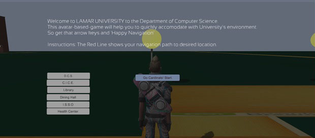
Figure 1. The welcome screen of our implementation
Figure 2 shows the avatar after he/she chooses to go to the Maes Building.
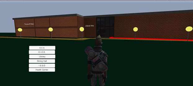
Figure 2. A front view of the Maes Building, which includes Department of Computer Science
Figure 3 represents the navigation path to the Computer Science department office inside the Maes Building after selecting option “D.C.S.”
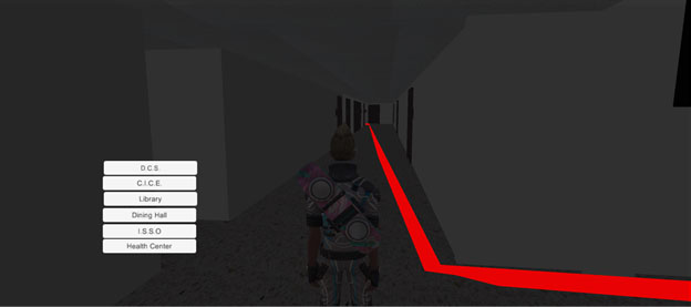
Figure 3. An inside view of the Maes Building along with Navigation Path
Figure 4 represents the avatar standing outside and in front of Mary and John Gray Library after selecting the option “Library”.
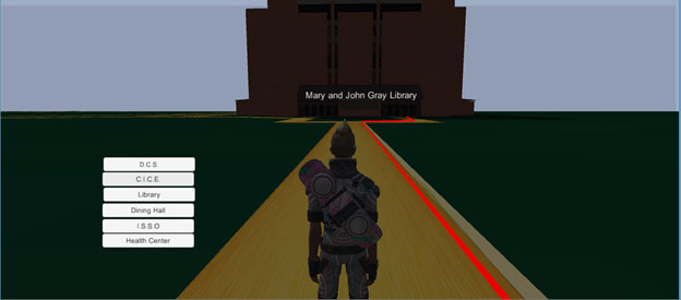
Figure 4. The front view of the Mary and John Gray Library
Figure 5 exhibits the study environment that allows students to have group discussions and brainstorming. Also, the separate study rooms give students the opportunity to work in silence.
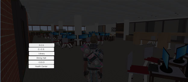
Figure 5. An inside view of the Library
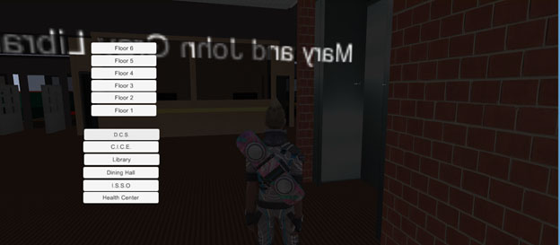
Figure 6. The avatar standing facing towards the Reception Desk in Library
Figure 7 steers the direction towards the Brooks-Shivers dinning hall after clicking on Dinning Hall button. The Dinning hall powered by Chartwell, provides a variety of cuisines to eat including vegetarian, non-vegetarian, and a variety of beverages like juices, fountain drinks, iced tea and also desserts.
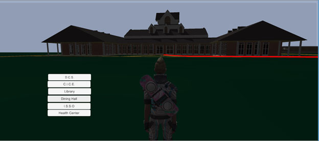
Figure 7. The avatar towards the Brooks and Shivers Dining Hall
Figure 8 adapts the inside view of the dinning hall. The 25,000-square-foot dining hall’s design blends with the architectural style of adjacent Cardinal Village. Inside is 13,000 square feet of dining area. Furnishings of booths, barstool seating, tables and a variety of mod chair styles will add atmosphere.
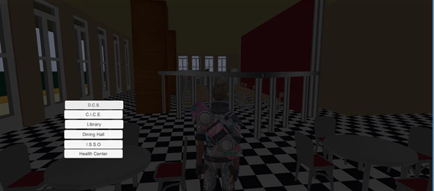
Figure 8. An inside view of the Brooks and Shivers Dining Hall
Figure 9 displays the Student Health Center. Its primary goal is to promote the health and wellness of the university population by offering medical and psychological services to the students of Lamar University.
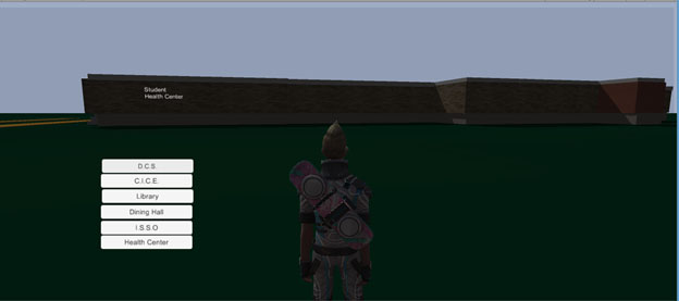
Figure 9. A view of the Student Health Center
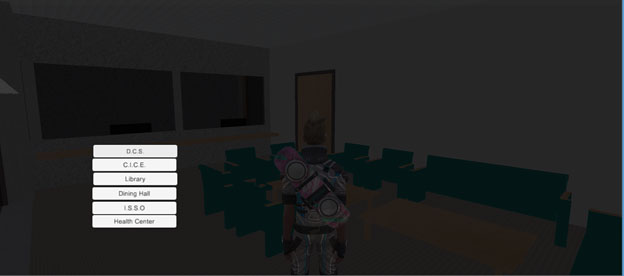
Figure 10. A student inside the Student Health Center
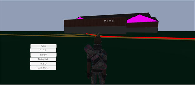
Figure 11. A front view of the most awaited building Center for Innovation and Commercialization Entrepreneurship (CICE)
Figure 12 exhibits Wimberley building that includes the International Student Services Office (I.S.S.O.), the Cashier office, the transcripts window etc.
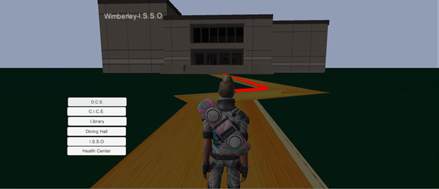
Figure 12. A student outside the Wimberley building
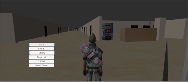
Figure 13. A student inside the Wimberley building
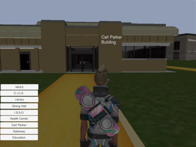
Figure 14. A student outside the Carl Parker Building
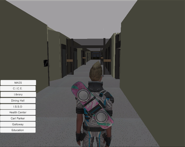
Figure 15. A student inside the Carl Parker Building
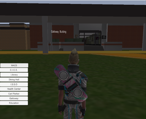
Figure 16. A student outside the Galloway Business building
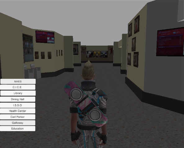
Figure 17. A student inside the Galloway Business building
Figure 18. A student outside the Education building
Figure 19. A student inside the Education building
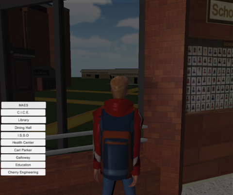
Figure 20.Partial views of Mary and John Gray Library and Carl Parker buildings from the 2nd floor of Cherry Engineering building
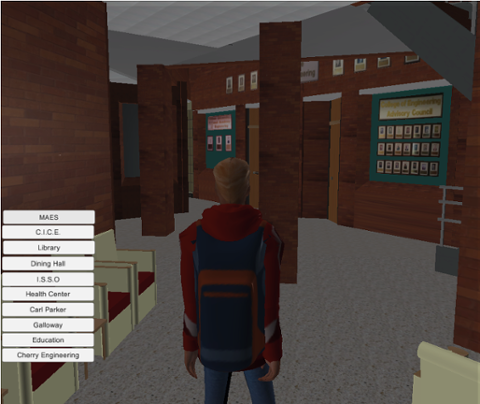
Figure 21.The student seating area of the first floor of the Cherry Engineering building
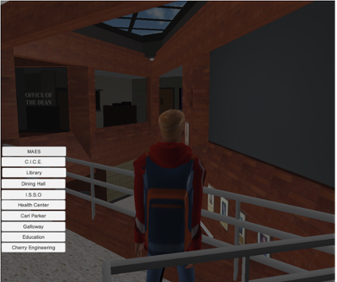
Figure 22.Student standing on the second floor of the Cherry Engineering building
8. Implementation
The software process of this project is based upon the Agile development model (Figure 20).
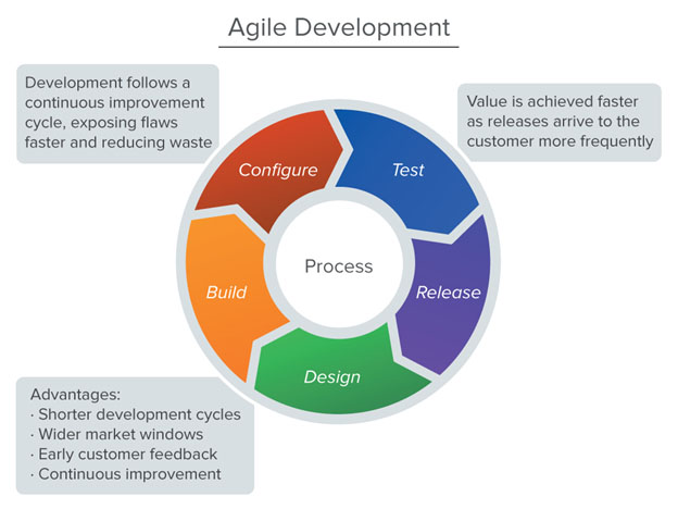
Figure 23. The Agile development model
8.1 Guidelines that drive the implementation and analysis
- Any difficulty in design, coding and testing a modification should signal the need for redesign or re-coding.
- Modifications should fit easily into isolated and easy-to-find modules. If they do not, some redesign may be needed.
- Modifications to tables should be very easy to make. If any table modification is not quickly and easily done, redesign is indicated.
- Modifications should become easier to make as the project progresses. If they are not, there is a basic problem such as a design flaw or a proliferation of patches.
- Patches should normally be allowed to exist for only one or two iterations. Patches may be necessary to avoid redesigning during an implementation phase.
- The existing implementation should be analyzed frequently to determine how well it measures up to project goals.
- Program analysis facilities should be used whenever available to aid in the analysis of partial implementations.
- User reaction should be solicited and analyzed for indications of deficiencies in the current implementation.
8.2 Advantages of the Agile model
- Feedback from early improvements improves later stages.
- The possibility of changes in requirements is reduced because of the shorter time span between the design of a component and its delivery.
- Users get benefits earlier than with a conventional approach.
- Early delivery of some useful components improves cash flow, because you get some return on investment early on.
- Smaller sub-projects are easier to control and manage.
- “Gold-plating‟, that is, the request of features that are unnecessary and not in fact used, is less as users will know if a feature is not in the current increment then it can be included in the next.
- The project can be temporarily abandoned if more urgent work crops up so job satisfaction is increased for developers.
9. Diagrams
i) Initially, when the Avatar based game starts, the state of the Player is Idle i.e., Player_IDLE.
ii) When the user selects the building, it enables the navigation path towards the destination.
iii) If the user selects any arrow keys (Right, Left & Up), the state of the player will change to running (i.e.: Player_Running). Also the path will be diminishing along with the player movement, hence the state of navigation path will change to Changing_Path.
iv) The path will also be diminishing along with the player’s movement, hence, the state of navigation path will change to Changing_Path. If no arrow keys are selected the state of path will again change to idle as the path is not changing.
v) If no arrow keys are selected, the state of player will change to Player_IDLE.
vi) If the rightmost close button of the game is selected, the avatar-based game will stop.
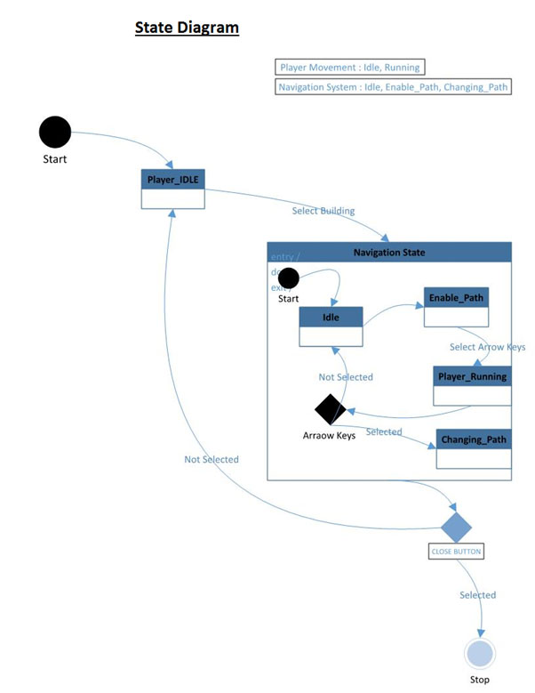
Figure 24. The state chart for player movement and the navigation system
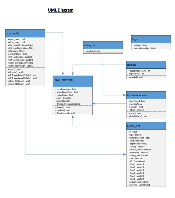
Figure 25. The class diagram for player and camera movement
10. Conclusion
This report introduced the design of the Avatar–based virtual campus tour. It explained the design, methodology, implementation and working set of the program. In our regular periodic meetings, we will follow an agile software developing process. With a rapid prototyping, we will convert each physical building into avatar-based virtual building. Our team is dedicated to working on future enhancements and constantly keeping an eye on new requirements that can be helpful to everyone.Future Enhancements
The following improvements will be considered as future work.
- Better Navigation
- Android Application for Avatar-based Lamar university virtual campus
- New Buildings of campus
- Website (Public domain, available online)
References
- 2015 Unity Technologies. www.Unity3d.com/commUnity, [accessed on February 20, 2015]
- Bimlesh Wadhwa, Stefan Andrei, Soo Yuen Jien. Software Engineering. An Object-Oriented Approach. McGraw-Hill, Revised Edition, 2007.
- blogs.Unity3d.com/category/services/ [accessed on March 12, 2015]
- docs.Unity3d.com/Manual/class-NavMeshAgent.html [accessed on April 5, 2015]